3D Robot Vision: What VISION 2026 Means for Bin Picking
 airobot_admin
•
Workstation Hardware Research
•
Updated October 25, 2026
•
13 min read
Performance intelligence for workstation buyers.
Machine vision / October 2026 analysis 3D robot vision: move from impressive demonstrations to reliable picking 3D robot vision is central to a difficult automation question: can a robot identify a usable grasp when objects are reflective, transparent, thin or randomly arranged? Mech-Mind's VISION 2026 demonstrations…
Machine vision / October 2026 analysis
3D robot vision: move from impressive demonstrations to reliable picking
3D robot vision is central to a difficult automation question: can a robot identify a usable grasp when objects are reflective, transparent, thin or randomly arranged? Mech-Mind’s VISION 2026 demonstrations make this a timely buying discussion for warehouses and factories.
This guide explains what the recent announcement supports, how to compare camera options and which checks should come before a purchase.
Read the news analysis Discuss a vision projectWhat VISION 2026 means for 3D robot vision
In its report published on 10 October 2026, Mech-Mind described demonstrations at VISION 2026 in Stuttgart, held from 6–8 October. The report covered transparent-object picking, sheet-metal handling and tire-code inspection, alongside camera developments for demanding imaging tasks.
The company also highlighted Mech-Eye ULTRA M-GL, previewed Range XL-GL and described UHP-040-5M-GL for miniature-component imaging. These are manufacturer-reported developments. They do not establish equivalent capabilities for every existing Mech-Eye model.
Read Mech-Mind’s official VISION 2026 report.
For buyers, the significance of 3D robot vision is practical: difficult surfaces and awkward presentation may deserve another feasibility assessment. The announcement is a reason to test a process, rather than evidence that every part can now be picked reliably.
Have a difficult picking application?
Send photographs of the actual parts and containers, their dimensions and materials, and the available mounting positions. Ask for a camera and software scope matched to those conditions.
Request vision-system guidanceIndustrial 3D cameras: what the robot needs from the image
Industrial 3D cameras provide spatial information about the scene. The application still needs to determine which data belongs to an object, where a tool can contact it and whether the robot can complete the movement. A visually detailed point cloud is useful only when it supports the required task.
For 3D robot vision, begin with the grasp surface. A suction tool may need a sufficiently continuous patch, while a finger gripper needs accessible contact locations and clearance. Missing points on those areas can matter more than missing detail elsewhere on the object.
Consider a shiny part beside a bin wall. The camera may identify much of its visible shape while the proposed grasp remains blocked. Alternatively, a transparent package may have an identifiable outline but unreliable depth where the tool needs to land. The acceptance test should expose these cases.
Ask the integrator to explain how image quality becomes a valid grasp. Keep the capture, object recognition, grasp selection and reachability stages visible in the proposal. This makes a failed attempt easier to diagnose and prevents every problem being attributed to the camera.
Mech-Eye cameras: match the exact model to the task
The VISION report is particularly relevant to buyers evaluating Mech-Eye cameras, but model names and supplied revisions must remain precise. ULTRA M-GL, PRO M-GL and PRO S-GL are different designations. A capability reported for one should not be copied into another product’s quotation.
In 3D robot vision procurement, request the full manufacturer model, hardware revision and matching datasheet. If a seller uses a regional or legacy name, obtain written confirmation of the corresponding configuration rather than treating similar naming as proof of equivalence.
| Report reference | Application emphasis | Buyer action |
|---|---|---|
| Mech-Eye ULTRA M-GL | Thin parts and transparent-object imaging. | Test the actual material and required grasp detail. |
| Mech-Eye Range XL-GL | Previewed long-range imaging development. | Confirm release status, exact specification and supply. |
| Mech-Eye UHP-040-5M-GL | Miniature precision-component imaging. | Match the working volume and required feature size. |
These references come from the official post-show report. They are not a claim that AI Robot Supplier stocks the newly described models. Confirm sourcing, release status and support for the exact offer.
The previously researched PRO M-GL Color 2000 enquiry requires its own revision check. Its family-level figures should not be replaced with the specifications of a newer model simply because both appear in the same camera range.
Robot bin picking starts with the complete working volume
Robot bin picking should be evaluated at the top, bottom, edges and corners of the container. The easiest image is not necessarily the condition that limits the process. A low remaining layer can expose blind areas, difficult approach angles and objects that were hidden during the first picks.
A 3D robot vision study should therefore include a dimensioned layout. Record the camera position, bin opening, highest object and lowest remaining layer. Add the robot, tool and any surrounding structure that could obstruct either imaging or motion.
Check useful coverage rather than nominal coverage alone. A point may lie inside the published field of view while the required grasp surface remains hidden. Similarly, the camera may see an object that the gripper cannot enter the bin to retrieve.
Decide what happens to the final unpicked items. A process that regularly leaves difficult parts for an operator can still be commercially useful, but that remaining work belongs in the throughput and staffing calculation. Record it explicitly instead of excluding it from the demonstration.
Compare camera distance, resolution and application scope
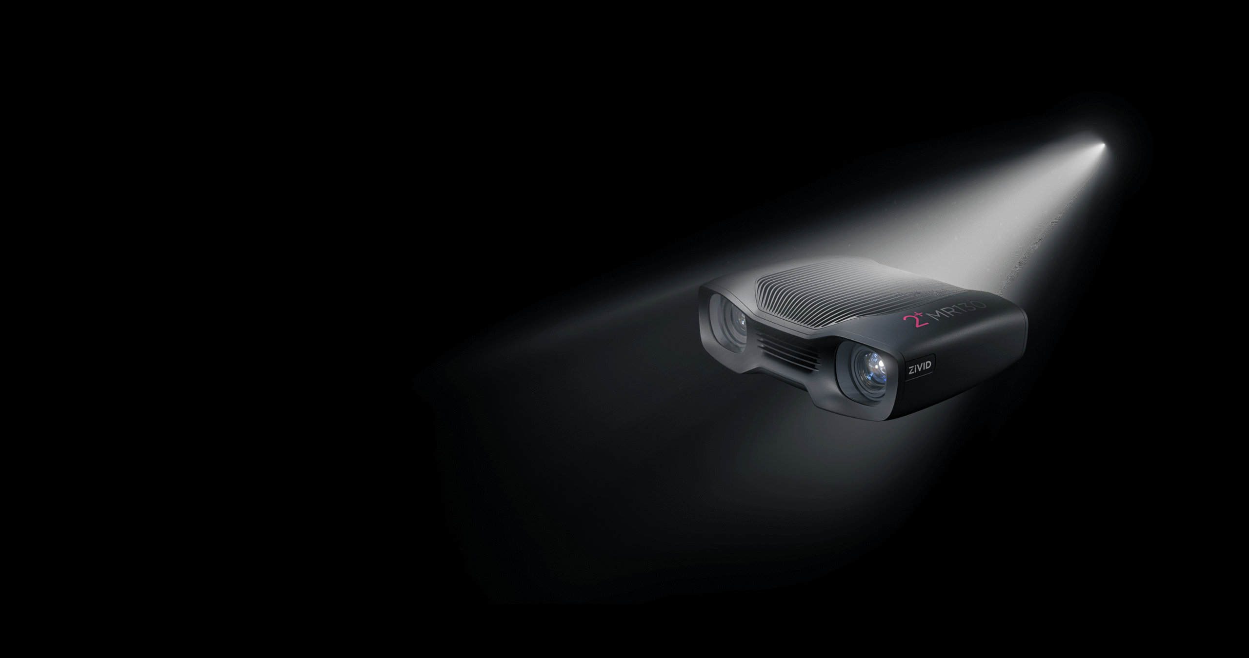
Two camera references already researched for the catalogue are Zivid 2+ MR130 and Zivid 3 XL250. They illustrate why industrial 3D cameras should be compared by working geometry rather than resolution alone.
| Reference | Zivid 2+ MR130 | Zivid 3 XL250 |
|---|---|---|
| Image resolution | 2448 × 2048 pixels. | 2816 × 2816 pixels. |
| Distance reference | 800–2700 mm published working range. | 1500–4000 mm recommended working distance. |
| Focus distance | 1300 mm. | 2500 mm. |
| Selection question | Does the scene provide useful detail for the intended piece-picking volume? | Does the mounting position cover the required large-bin or pallet volume? |
Sources: the MR130 technical specification and XL250 technical specification. Working-range and recommended-distance descriptions are not identical performance guarantees.
For 3D robot vision, compare the result at your proposed installation distance. Ask for the same objects and acceptance criteria across candidate cameras. A favourable example from a different scene does not establish the best fit for your application.
Transparent, reflective and dark materials need separate trials
A successful trial on one difficult surface does not establish performance on every difficult material. Transparent packaging, polished metal and dark components can create different imaging problems. Test each important material group in its normal condition and presentation.
For transparent products, inspect the useful depth at the intended contact area. For reflective parts, include changes in orientation and nearby surfaces. For dark objects, evaluate the required detail without assuming that a recognisable colour image guarantees a usable depth result.
The XL250 datasheet specifically identifies limits for extremely transparent materials, including some thin films and optical-grade glass. That is a useful reminder that 3D robot vision coverage must be defined using actual samples and documented exclusions.
Keep difficult examples in the acceptance set even if they represent a small proportion of daily work. Those items can consume a disproportionate amount of recovery time. Where a material remains unsupported, define its route through the process before the system enters production.
Vision-guided robotics needs software beyond the camera
Vision-guided robotics connects image acquisition to an executable robot task. The proposal should explain how objects are recognised, how grasp candidates are generated and how collision and reachability checks are performed before motion.
Mech-Vision and Mech-Viz address different parts of that workflow. Mech-Mind presents Mech-Vision as machine-vision software and Mech-Viz as robot-programming software with motion-planning functions. Confirm the separate licence and integration scope rather than assuming that a camera includes every required software product.
A 3D robot vision system also needs a defined coordinate chain. The application must relate camera measurements to the robot and the work area. Ask who performs calibration, how it is checked and what happens after the camera or fixture is moved.
Specify the response to no detection, multiple plausible detections and an unreachable grasp. A useful system should identify these conditions clearly enough for the cell to retry, select another item or request assistance. Silent failure is difficult to support.
Measure the complete 3D robot vision timing pipeline
Camera acquisition time is one part of the process. The application may also need transfer, reconstruction, recognition, grasp planning, robot communication and movement. Define which stages a quoted time includes before comparing performance figures.
For a 3D robot vision trial, record when acquisition begins, when usable data is available and when a valid robot task is ready. Then record the completed transfer separately. This distinguishes a perception delay from a long robot path or a slow recovery procedure.
Keep the host hardware and capture settings with every result. A timing figure obtained on a development computer with one capture profile should not be transferred to a different production configuration without checking it.
Measure difficult scenes as well as typical scenes. If the application needs repeated captures or slower settings for certain materials, include those events in the operating rate. A short best-case sequence is not a sustained throughput result.
7 essential 3D robot vision checks for better picking
- Define the object set. Include dimensions, mass, surface finish, packaging, fragility and difficult examples.
- Map the working volume. Show camera position, bin dimensions, highest and lowest objects, and robot clearance.
- Test the grasp surface. Inspect the data where the tool needs to make contact, not just the overall object outline.
- Confirm the software chain. Itemise acquisition, recognition, grasp planning, motion planning and communication responsibilities.
- Measure end-to-end timing. Separate acquisition, result availability, planning, movement and exception recovery.
- Agree acceptance criteria. Record correct transfers, unsupported items, damage, retries and operator interventions.
- Price the complete lifecycle. Include integration, calibration, licences, maintenance, training and support.
These seven checks turn a 3D robot vision quotation into something the project team can evaluate. Use the same criteria across proposals so that differences in price reflect an understandable difference in scope or evidence.
Request a camera and integration shortlist
Provide the layout, sample objects, desired task and current robot/controller. Ask which camera, software and computing configuration is proposed, and which assumptions still require testing.
Discuss your bin-picking requirementsBuild a repeatable acceptance test for industrial 3D cameras
Start with a representative sample set and retain a smaller reference set that can be rerun after configuration changes. Keep object preparation consistent. If parts are manually separated, cleaned or specially positioned, record that preparation as part of the process.
A 3D robot vision report should distinguish recognition success from successful handling. The camera may provide a correct pose while the gripper fails to hold the item. Alternatively, the robot may move an object successfully while the application records the wrong item or destination.
| Test area | Include | Record |
|---|---|---|
| Scene variation | Different fill levels, orientations and overlaps. | Detection failures and unreachable grasps. |
| Material variation | Representative reflective, dark and transparent examples. | Missing grasp-surface data and required setting changes. |
| Handling quality | The actual tool, transfer path and destination. | Dropped, damaged or incorrectly transferred items. |
| Recovery | Failed picks, no detections and normal restarts. | Retries, operator time and skills required. |
| Reproducibility | The same reference set after a controlled change. | Hardware, software, settings and calibration state. |
Agree the test duration and permitted exclusions before the run. A supplier and customer can both report a high success rate while counting different events. Explicit definitions make the result more useful than an isolated percentage.
Keep calibration and maintenance in the deployment plan
Commissioning does not end when the first object is picked. A 3D robot vision system needs a practical way to check that its geometry and image quality remain suitable after normal maintenance or accidental movement.
Define who can change capture settings, update recognition models or move the camera. Keep an approved configuration backup and a short reference test. If behaviour changes, the team should be able to identify what changed before adjusting several unrelated parameters.
Include access for cleaning, inspection and replacement in the mounting design. A camera positioned for a good view can still be awkward to service. Agree how downtime is handled and who restores the complete application after a component replacement.
Compare the installed cost of 3D robot vision
A camera price does not describe the installed cost. The proposal may also require mounting, cables, power, network equipment, host computing, software licences, calibration, robot integration and acceptance testing. Compare equivalent supplied scopes.
The value of 3D robot vision should be tied to the work completed. Measure supported assortment, correct transfers, remaining manual work and recovery time. A system that handles a narrower set reliably may be more useful than one with broader claims and unclear exclusions.
For research projects, include the engineering needed to turn sample captures into a maintained application. For production, include training, support and the process for adding new items. These costs can affect the decision as much as the initial component price.
When evidence is incomplete, stage the project: sample capture, feasibility study, integrated trial and acceptance run. Each stage should answer a specific question before the next commitment is made.
Equipment links for a 3D robot vision project
The following internal links support the wider project discussion. They are planning references and do not imply that the products form a validated camera, robot and software bundle.
- Universal Robots UR20 collaborative robot for a separately checked reach, load and integration assessment.
- NVIDIA Jetson AGX Thor Developer Kit for development computing where the selected software supports the platform.
- NVIDIA DGX Spark 128GB 4TB for an independently validated development or processing environment.
- Robot accessories for mounting, tooling and the broader installation discussion.
- Ask about Zivid cameras, Mech-Eye cameras and vision-software sourcing with the exact model and application requirements.
- International industrial-robot buying guide for the wider procurement process.
For 3D robot vision enquiries, include the destination, quantity, target date, current equipment and required acceptance result. Request written confirmation of package contents, supply route and support responsibilities.
3D robot vision frequently asked questions
What is 3D robot vision?
It is the use of spatial scene information to support robotic tasks such as locating objects and planning grasps. The complete application also requires recognition, coordinate calibration, robot integration and a way to confirm that the task was completed correctly.
Are industrial 3D cameras complete bin-picking systems?
No complete system is implied by a camera-only offer. Identify the software, host computer, robot, gripper, calibration, safeguarding and commissioning scope separately. Ask who takes responsibility for the integrated result.
Can robot bin picking handle transparent packaging?
Some manufacturers describe solutions for transparent objects, but coverage depends on the actual material, presentation and required grasp. Test representative packaging and document unsupported cases instead of assuming universal performance from a demonstration.
Are all Mech-Eye cameras equivalent?
No. Match the full model designation, optical configuration and hardware revision to the intended task. Capabilities described for a newly announced model should not be transferred to a different camera in the range.
Is higher megapixel resolution always better?
Resolution is one selection factor. Working distance, field of view, useful surface data, calibration and application requirements also matter. Compare the result at the actual installation geometry rather than selecting from pixel count alone.
Does acquisition time equal the picking cycle?
No. A completed pick can also involve transfer, reconstruction, recognition, grasp planning, robot movement and recovery. Confirm which stages a published timing figure includes and measure the integrated process.
What software does vision-guided robotics require?
The answer depends on the architecture. Define acquisition, recognition, grasp selection, motion planning and robot communication. Confirm separate software licences and supported versions rather than assuming every function is bundled with the camera.
Can an existing robot be upgraded with 3D robot vision?
Potentially, but confirm controller interfaces, supported drivers, tool geometry, calibration and working-volume requirements first. An upgrade proposal should identify reusable equipment and the engineering needed to validate the complete task.
How much does a 3D robot vision system cost?
Request an application-specific quotation covering hardware, licences, integration, testing and support. Compare equivalent installed scopes. This article does not provide an unverified selling price or imply that an arm-only or camera-only price covers the complete cell.
What should I send with a camera enquiry?
Provide part photographs, dimensions, materials, container drawings, mounting distances, lighting conditions and the required handling task. Include difficult samples, existing robot/controller details, destination and the acceptance criteria the project needs to meet.
Official 3D robot vision sources
- Mech-Mind’s official VISION 2026 report .
- Mech-Viz robot-programming information .
- Zivid 2+ MR130 official product information .
- Zivid MR130 technical specification .
- Zivid 3 official product information .
- Zivid 3 XL250 technical specification .
Research checked on 25 October 2026. Manufacturer developments and specifications are attributed to official sources. Application examples are evaluation scenarios, not claimed hands-on tests or guaranteed customer results.
Turn the news into a testable specification
Plan your 3D robot vision project
Send your parts, container layout, working distances and target task. Ask AI Robot Supplier to discuss camera, software and equipment options with a clear validation and sourcing scope.
 ZOTAC GAMING GeForce RTX 5090 AMP Extreme INFINITY
 PNY GeForce RTX 5070 Ti 16GB ARGB EPIC-X RGB Overclocked Triple Fan
 NVIDIA GeForce RTX 3090 Founders Edition 24GB
 Sapphire NITRO+ Radeon RX 7800 XT 16GB