Cobot Payload Selection Guide for Enterprise Buyers
 •
Robotics Research
•
Updated October 14, 2026
•
7 min read
•
Robotics Research
•
Updated October 14, 2026
•
7 min read
Automation intelligence for serious technology buyers.
Use this cobot payload selection guide to compare arm capacity, tooling, reach, safety, and duty cycle before requesting a supplier-confirmed quote today.
A cobot rated for 10 kg is not automatically suitable for a 10 kg application. The end-of-arm tool, cable package, workpiece center of gravity, movement profile, and process forces all affect whether the robot can run safely and repeatedly. This cobot payload selection guide helps engineering and procurement teams define the real requirement before comparing models or requesting a supplier-confirmed configuration.
Start With the Complete Moving Load
Payload is the mass carried by the robot at its flange. For a production deployment, that figure must include every item moving with the arm: gripper or tool, adapter plate, sensors, pneumatic fittings, hoses, cable dress pack, and the part being handled. Buyers often begin with the workpiece weight alone, which can understate the true load substantially.
For example, a 7 kg carton may require a 2.5 kg vacuum gripper, a 0.8 kg adapter, and 0.5 kg of fittings and cabling. The application payload is therefore 10.8 kg before accounting for any retained material, such as a filled container, fixture, or multiple picked parts. Selecting a 10 kg cobot for this task would create an immediate specification conflict.
Use the maximum moving mass, not the average mass. If a system picks products in several sizes, calculate the requirement around the heaviest approved product and the heaviest approved end effector. This provides a clearer basis for a formal quotation and avoids a deployment where the cobot can only handle part of the expected SKU range.
Rated Payload Is Only One Selection Limit
A payload rating is generally measured under defined conditions. It does not mean the arm can carry that mass at every reach, speed, orientation, or center-of-gravity position. Manufacturers may publish payload curves, reach-dependent limits, and permitted moments of inertia. These values should be reviewed alongside the headline payload specification.
Center of gravity changes the load on each joint
A compact 10 kg load positioned close to the flange is easier to control than the same 10 kg load extending 300 mm from the flange. As the center of gravity moves outward, the torque applied to the wrist and upstream joints increases. Long tools, deep cartons, machine-tending grippers, and multi-part fixtures can therefore require a larger robot than their mass alone suggests.
Ask the integrator or manufacturer to validate the tool’s center-of-gravity coordinates in the robot’s flange reference frame. The most useful documentation states the mass, distance from the flange, orientation, and whether that center of gravity shifts during the cycle. A vacuum gripper that handles differently sized boxes, for instance, may have a changing center of gravity between picks.
Inertia matters when the cycle is fast
Mass describes how heavy a load is. Inertia describes how resistant that load is to acceleration and deceleration. A long or irregular tool may have acceptable mass but excessive inertia for a fast pick-and-place cycle. The result can be reduced speed, position error, protective stops, or limits imposed by the robot controller.
This is especially relevant for palletizing, high-speed packaging, laboratory automation, and machine tending with extended grippers. Provide the required cycle time, travel distances, acceleration expectations, and the geometry of the tool and part. A supplier can then confirm whether the target cycle is realistic rather than simply confirming that the payload rating appears sufficient.
Evaluate the Work at Full Reach and Worst Orientation
Payload capacity is rarely a single number in practical operation. The most demanding position may be at maximum horizontal reach, overhead, below the mounting plane, or at a wrist angle used only briefly during a transfer. A cobot may perform well near its base but slow down or reach a joint limit at the edge of the work envelope.
Map the actual pick and place points before selecting the arm. Include the highest and lowest locations, the farthest reach, tool clearance around fixtures, and approach paths around guarding or equipment. If the application involves loading a CNC machine, confirm not only that the cobot can reach the chuck, but also that the gripper can enter the machine safely without collision or cable interference.
Mounting orientation also affects the selection. Wall-mounted, ceiling-mounted, angled, and mobile-base installations can introduce model-specific limitations. Some cobots permit these configurations with adjusted payload or speed limits, while others require manufacturer approval. Do not assume a floor-mounted rating applies unchanged to every installation position.
Account for Process Forces, Not Just Handling Weight
Material handling is only one cobot application. Screwdriving, sanding, dispensing, polishing, cutting, drilling, and inspection can apply external forces and moments to the arm. These forces add to the dynamic load created by the payload itself.
A screwdriving tool may be light, but reaction torque and axial force during fastening must be evaluated. A sanding application can create fluctuating lateral loads. A dispensing nozzle may require modest payload capacity but demand high path accuracy at a specific speed. In each case, the cobot selection should be based on the complete process requirement, including force, torque, repeatability, compliance device behavior, and duty cycle.
Safety settings can add another constraint. Collaborative operation may require reduced speed and force limits based on the risk assessment. If the cycle only meets target throughput at speeds that are not appropriate for the collaborative workspace, a larger cobot or a different cell layout may be required. The right answer depends on the task, safeguarding concept, and applicable safety validation, not on payload alone.
Build a Practical Payload Margin
A reasonable margin helps accommodate production variation, future tooling changes, and performance losses caused by difficult motion profiles. It should not be treated as a fixed percentage for every project. A simple, slow transfer with a centered load may need less margin than a high-speed application with a long gripper and frequent changes in direction.
Avoid oversizing without purpose. A higher-payload cobot can increase purchase cost, footprint, power requirements, and the complexity of the safety design. It may also be less appropriate where a compact arm must work inside a restricted machine envelope. The objective is not to buy the largest available model. It is to procure a platform with verified capacity for the full operating envelope.
A practical review should compare the following information as a package:
- Maximum combined moving mass, including tool, adapters, cabling, and workpiece
- Center-of-gravity location and any shift between product variants
- Tool and workpiece geometry, with estimated moments of inertia
- Required reach, mounting orientation, and the worst-case robot pose
- Cycle time, acceleration, duty cycle, and expected throughput
- Process forces, torque, environmental conditions, and safety constraints
Make Payload Data Procurement-Ready
For business buyers, payload selection is not complete when a technical team identifies a likely robot model. The information should be converted into a documented configuration request that can be commercially confirmed. This reduces the risk of receiving an arm that is technically capable on paper but incomplete for the intended cell.
State whether the purchase includes the robot arm, controller, teach pendant, power and communication cables, mounting hardware, end-of-arm tooling, vision hardware, force-torque sensor, software licenses, and any mobile base or safety equipment. Accessories can materially change both payload and integration scope. Warranty terms, condition, lead time, delivery method, and included accessories should be confirmed at the product level.
For multi-unit deployments, ask whether the quoted configuration is consistent across the fleet and whether the supplier can confirm controller version, regional power requirements, software compatibility, and spare-part availability. A fleet-ready purchase benefits from standardized tooling interfaces and documented payload assumptions, particularly when sites will operate different product mixes.
At AI Robot Supplier, a high-value robotics request can be handled through direct checkout where available, a formal quotation, or supplier-confirmed sourcing for deployment-specific requirements. Providing complete payload and application data early makes that confirmation more accurate and commercially accountable.
When a Larger Cobot Is Not the Best Fix
If the payload calculation exceeds the preferred cobot’s capacity, a larger model is one option, but it is not the only option. Reducing tool mass, shortening an adapter, relocating a vacuum generator, using a lighter gripper, or changing the pick orientation can lower joint loading. Splitting a multi-part pick into two motions may also allow a smaller arm to meet the requirement, although it can affect throughput.
Conversely, reducing the stated load is not a valid solution if it compromises production needs. The selected system must support the actual workpiece range, expected cycle, and foreseeable operating conditions. The most reliable payload decision is the one supported by documented load data, a validated reach study, and a supplier-confirmed configuration before the purchase order is released.
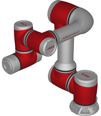 JAKA Zu 7 Collaborative Robot
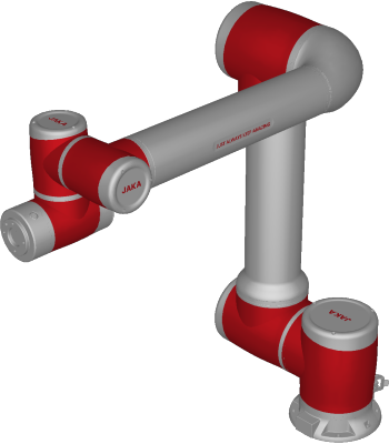 JAKA Zu 12 Collaborative Robot
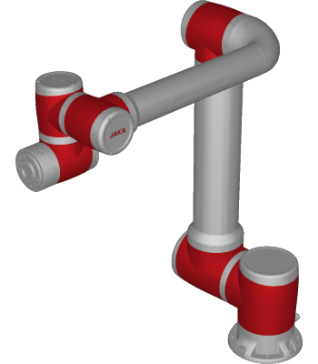 JAKA Pro 16 Collaborative Robot
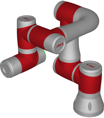 JAKA Zu 3 Collaborative Robot